Lancashire Boiler


It is a stationary, fire tube, internally fired boiler. The size is approximately from 7-9 meters in length and 2-3 meters in diameter.

Construction of Lancashire Boiler:

It consists of

  1. Cylindrical shell
  2. Furnace tubes, bottom flue and side flues
  3. Grate
  4. Fire bridge
  5. Dampers


Cylindrical shell

It is placed in horizontal position over a brick work. It is partly filled up with water. The water level inside the shell is well above the furnace tubes.

Furnace tubes, bottom flue and side flues:

Two large internal furnace tubes (flue tubes) extend from one end to the other end of the shell. The flues are built-up of ordinary brick lined with fire bricks. One bottom flue and two side flues are formed by brick setting, as shown in the figure.

Grate

The grate is provided at the front end of the main flue tubes. Coal is fed to the grate through the fire hole.

Fire bridge:

A brickwork fire bridge is provided at the end of the grate to prevent the flow of coal and ash particles into the interior of the furnace (flue) tubes. Otherwise the coal and ash particles carried with gases form deposits on the interior of the tubes and prevent the heat transfer to the water.

Dampers:

Dampers is in the form of sliding doors are placed at the end of the side flues to control the flow of gases from side flues to the chimney flue.

Working of Lancashire boiler


Coal is fed to the grate through the fire hole and is burnt. The hot gases leaving the grate move along the furnace (flue) tubes upto the back end of the shell and then in the downward direction to the bottom flue. The bottom of the shell is thus first heated.

The hot gases, passing through the bottom flue, travel upto the front end of the boiler, where they divide into two streams and pass to the side flues. This makes the two sides of the boiler shell to become heated. Passing along the two side flues, the hot gases travel upto the back end of the boiler to the chimney flue. They are then discharged into the atmosphere through the chimney.

With the help of this arrangement of flow passages of hot gases, the bottom of the shell is first heated and then its sides. The heat is transferred to water through the surface of the two flue tubes (which remain in water) and bottom and sides of the shell.

The arrangement of flues increases the heating surface of the boiler to a large extent.

Dampers control the flow of hot gases and regulate the combustion rate as well as steam generation rate.

The boiler is fitted with necessary mountings. Pressure gauge and water level indicator provided at the front. Safety valve, steam stop valve, low water and high steam safety valve and man-hole are provided on the top of the shell.

High steam low water safety valve:

It is a combination of two valves. One is lever safety valve, which blows-off steam when the working pressure of steam exceeds. The second valve operates by blowing-off the steam when the water level falls below the normal level.

Blow-off clock:

It is situated beneath the front portion of the shell for the removal of mud and sediments. It is also used to empty the water in the boiler during inspection.

Fusible plug:

It is provided on the top of the main flues just above the grate. It prevents the overheating of the boiler tubes by extinguishing the fire when the water level falls below a particular level. A low water level alarm is mounted in the boiler to give a warning when the water level falls below the preset value.

Salient features of Lancashire Boiler

The arrangement of flues in this boiler increases the heating surface of shell to a large extent.
It is suitable where a large reserve of steam and hot water is needed.
Its maintenance is easy.
Superheated can be easily incorporated into the system at the end of the main flue tubes. Thus overall efficiency of the boiler can be increased.

Note : The simple vertical Boiler, Cochran and Lancashire Boilers discussed till this post are Fire tube boilers. In the upcoming posts, I will write about water tube boilers namely Babcock and Wilcox Boiler.


Cochran boiler


It is a multi-tubular vertical fire tube boiler having a number of horizontal fire tubes. T is the modification of a simple vertical boiler where the heating surface has been increased by means of a number of fire tubes.

cochran boiler image
It consists of

  1. Shell
  2. Crate
  3. Fire box
  4. Flue pipe
  5. Fire tubes
  6. Combustion chamber
  7. Chimney
  8. Man-hole


Shell
It is hemispherical on the top, where space is provided for steam.

Grate
It is placed at the bottom of the furnace where coal is burnt.

Fire box (furnace )
It is also dome-shaped like the shell so that the gases can be deflected back till they are passed out through the flue pipe to the combustion chamber.

Flue pipe:
It is a short passage connecting the fire box with the combustion chamber.

Fire tubes:
A number of horizontal fire tubes are provided, thereby the heating surface is increased.

Combustion chamber:
It is lined with fire bricks on the side of the shell to prevent overheating of the boiler. Hot gases enter the fire tubes from the flue pipe through the combustion chamber.

Chimney:
It is provided for the exit of the flue gases to the atmosphere from the smoke box.

Manhole:
It is provided for inspection and repair of the interior of the boiler shell.

Normal size of a Cochran boiler:
Shell diameter – 2.75 meters:
Height of the shell – 6 meters.

Working of the Cochran boiler:

Coal is fed into the grate through the fire hole and burnt. Ash formed during burning is collected in the ashpit provided just below the grate and then it is removed manually.

The host gases from the grate pass through the flue pipe to the combustion chamber. The hot gases from the combustion chamber flow through the horizontal fire tubes and transfer the heat to the water by convection.

The flue gases coming out of fire tubes pass through the smoke box and are exhausted to the atmosphere through the chimney.
Smoke box is provided with a door for cleaning the fire tubes and smoke box.

The following mountings are fitted to the boiler:


Pressure gauge: this indicates the pressure of the steam inside the boiler.

Water gauge: this indicates the water level in the boiler. The water level in the boiler should not fall below a particular level, otherwise the boiler will be over heated and the tubes may burn out.

Safety valve: the function of the safety valve is to prevent an increase of steam pressure in the boiler above its normal working pressure.

Steam stop valve: it regulates the flow of steam supply to requirements.

Blow-off cock: it is located at the bottom of the boiler. When the blow-off cock is opened during the running of the boiler, the high pressure steam pushes (drains) out the impurities like mud, sand, etc., in the water collected at the bottom.

Fusible plug: it protects the fire tubes from burning when the water level in the boiler falls abnormally low.

Salient features of Cochran boiler:

  1. The dome shape of the furnace causes the hot gases to deflect back and pass through the flue. The un-burnt fuel if any will also be deflected back.
  2. Spherical shape of the top of the shell and the fire box gives higher area by volume ratio.
  3. It occupies comparatively less floor area and is very compact.
  4. It is well suited for small capacity requirements.

Simple vertical boiler:

The image shows the simplest form of an internally fired vertical fire-tube boiler. It does not require heavy foundation and requires very small floor area.

simple vertical boiler


Cylindrical shell:
The shell is vertical and it attached to the bottom of the furnace. Greater portion of the shell is full of water which surrounds the furnace also. Remaining portion is steam space. The shell may be of about 1.25 metres diameter and 2.0 meters height.

Cross-tubes:
One or more cross tubes are either riveted or flanged to the furnace to increase the heating surface and to improve the water circulation.

Furnace (or fire box):
Combustion of coal takes place in the furnace (fire box).

Grate:
It is placed at the bottom of fire box and coal is fed on it for burning.

Fire door:
Coal is fed to the grate through the fire door.

Chimney (or stack):
The chimney (stack) passes from the top of the firebox through the top of the shell.

Manhole:
It is provided on the top of the shell to enable a man to enter into it and inspect and repair the boiler from inside it. It is also, meant for cleaning the interior of the boiler shell and exterior of the compbustion chamber and stack (chimney).

Hand holes:
These are provided in the shell opposite to the ends of each cross tube for cleaning the cross tube.

Ashipt:
It is provide for collecting the ash deposit, which can be removed away at intervals.

Working:
The fuel (coal) is fed into the grate through the fire hole and is burnt. The ashpit placed below the grate collect the ashes of the burning fuel.

The combustion gas flows from the furnace, passes around the cross tubes and escapes to the atmosphere through the chimney.

Water goes by natural circulation due to convection currents, from the lower end of the cross tube and comes out from the higher end.

The working pressure of the simple vertical boiler does not exceed 70 N/cm^2.

The following mountings are fitted in the boiler:

Pressure gauge: it indicates the pressure of the steam inside the boiler.
Water gauge (water level indicator): this indicates the water level in the boiler.
Safety valve: it prevents an increase of steam pressure in theboiler above its design pressure.
Steam stop valve: it regulates the flow of steam supply to requirements.

Types of boilers:

Boilers can be classified as follows:

1. According to the flow of water and hot gases – fire tube (or smoke tube) and water tube boilers.

In fire tube boilers, hot gases pass through tubes which are surrounded with water. Examples: Vertical, Cochran, Lancashire and Locomotive boilers. There may be single tube as in case of Lancashire boiler or there may be a bank of tubes as in a locomotive boiler.

In water tube boilers, water circulates through a large number of tubes and hot gases pass around them. Eg., bobcock & Wilcox boiler.

2. According to the axis of the shell – vertical and horizontal boilers.

3. According to location or position of the furnace. Externally and internally fired boilers.

In internally fired boilers, the furnace forms an integral part of the boilers structure. The vertical tubular, locomotive and the scotch marine boilers are well known examples.

Externally fired boilers have a separate furnace built outside the boiler shell and usually below it. The horizontal return tube (HRT) boiler is probably the most widely known example of this type.

4. According to the application – stationery and mobile boilers. A stationary boilers is one of which is installed permanently on a land installation.

A marine boiler is a mobile boiler meant for ocean cargo and passenger ships with an inherent fast steaming capacity.

5. According to steam pressure – low, medium and high pressure boilers.


Types of boilers:


Fire Tube Boilers

Water Tube Boilers 

High Pressure Boilers

Geo-Thermal Power Plant:

It is also a thermal power plant, but the steam required for power generation is available naturally in some part of the earth below the earth surface. According to various theories earth has a molten core. The fact that volcanic action takes place in many places on the surface of earth supports these theories.
Geo-Thermal Power Plant

Steam well:
Pipes are embedded at places of fresh volcanic action called steam wells, where the molten internal mass of earth vents to the atmosphere with very high temperatures. By sending water through embedded pipes, steam is raised from the underground steam storage wells to the ground level.

Separator:
The steam is then passed through the separator where most of the dirt and sand carried by steam are removed.

Turbine:
The steam from the separator is passed through steam drug and is used to run the turbine which in turn drives the generator. The exhaust steam from the turbine is condensed. The condensate is pumped into the earth to absorb the ground heat again and to get converted into steam.

Location of plant, installation of equipment like control unit etc., within the source of heat and the cost of drilling deep wells as deep as 15,000 meters are some of the difficulties commonly encountered.

Tidal power generation:

Principle of Tidal power generation:
Tide or wave is periodic rise and fall of water level of the sea. Tides occur due to the attraction of sea water by the moon. Tides contain large amount of potential energy which is used for power generation. When the water is above the mean sea level, it is called flood tide. When water level is below the mean level it is called ebb tide.

Working of Tidal power generation:
The arrangement of this system is shown in image. The ocean tides rise and fall and water can be stored during the rise period and it can be discharged during fall. A dam is constructed separating the tidal basin from the sea and a difference in water level is obtained between the basin and sea.

During high tide period, water flows from the sea into the tidal basin through the water turbine. The height of tide is above the tidal basin. Hence the turbine unit operates and generates power, as it is directly coupled to a generator.


During low tide period, water flows from tidal basin to sea, as the water level in the basin is more than that of the tide in the sea. During this period also, the flowing water rotates the turbine and generates power.
The generation of power stops only when sea level and the tidal basin level are equal. For the generation of power economically using this source of energy requires some minimum tide height and suitable site. Kislaya power plants in France are the only examples of this type of power plant.

Advantages of tidal power plants

  1. It is free from pollution as it does not use any fuel.
  2. It is superior to hydro-power plant as it is totally independent of rain.
  3. It improves the possibility of fish farming in the tidal basins and it can provide recreational facilities to visitors and holiday makers.


Disadvantages of tidal power plants:

  1. Tidal power plants can be developed only if natural sites are available on the bay.
  2. As the sites are available on the bays which are always far away from load centers, the power generated has to be transmitted to long distances. This increases the transmission cost and transmission losses.
  3. The supply of power is not continuous as it depends upon the timing of tides.
  4. The navigation is obstructed.
  5. Utilization of tidal energy on small scale is not economical.


Wind power Generation

The primitive man had to use his muscle power to carry out different works in his attempt of obtaining the necessities of life. The demand for more power and the scarcity of man power and the ready availability of natural resources like wind, water, etc., might have formed the reason why the ancient man turned his attention to the utilization of these resources as sources of power; thus originated the early prime movers namely wind mill and water wheel.

Principle of wind mill:
Wind flow is created as an effect of solar heat. Winds are caused due to the absorption of solar energy on the earth surface and the rotation of earth about its own axis and around the sun. because of this, alternate heating and cooling occurs and difference in pressure is obtained and the air movement is caused.

The flowing wind which has kinetic energy is used to rotate the wind turbine which is also known as wind mill. Although wind mills have been used for more than a dozen centuries for pumping water and grinding grains, interest in large scale power generation had developed over the past 50 years.

The earth’s atmosphere is thus a marvelous solar driven heat engine. It is estimated that roughly 10 million MW of energy is continuously available in the earth’s winds.

Types of winds mills
Wind mills are classified as

  • Horizontal axis type and
  • Vertical axis type,  Depending on their axis of rotation.


Horizontal axis wind mills are further classified as single-bladed, double-bladed and multi-bladed types.

Horizontal axis wind mill with double blade rotor:
In the horizontal axis single blade type, the blade is of propeller type with counter weight arrangement. The double blade type gives a better performance than the single blade type.

In the double-blade type, the blade has thick cross section of an aerofoil. At the tip of the blade, the velocity is about six times the wind velocity. The blade is set at right angles to the direction of the wind. Ideally the blades should be twisted, but because of construction difficulties this is not always achieved.
The blade rotor drives a generator through a gear box. It is mounted on a bed plate attached on the top of the tower.

Blade material: the blades are made from aluminum or sheet metal. Not a single large wind turbine – generator with metal blades has operated for longer than one year without a blade failure. The suitable material required is a major problem in developing wind mills of higher power generation capacity.

With rotor, the tower is also subjected to the wind loads which may cause serious damage. Hence the structure of the tower should be so designed to withstand the wind load.

The best sites for the wind energy are found off-shore and sea coast. The second best sites are in mountains. The lowest level of wind energy is found in plains, where values are generally three or four times lower than that at the coast.

Multiblade rotor:
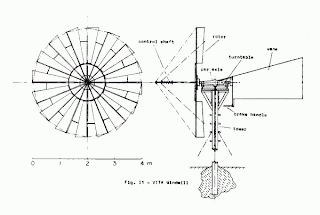
It is shown in image below. Rotors with more than two blades will produce high power.

Sail type blades:
It is of recent origin. The blade surface is made from cloth, nylon or plastic arranged as sail wings. There is also variation in the number of sails used.

The horizontal axis types generally have better performance than vertical types. They are mainly used for power generation and pumping water. The biggest wind mill erected for power generation is of 2500kW capacity in U.S.A.

Advantages of Wind Power Generation:

  1. The wind energy is a renewable source of energy. It is free and inexhaustible.
  2. The power requirements for irrigation, lighting and small industrial units can be fulfilled with the use of wind energy. Power generation on large scale using wind energy is not yet so successful, but the small wind mills will play a vital role in the present condition of power shortage.
  3. It does not need transportation.
  4. Like all forms of solar energy, wind power systems are non-polluting.


Disadvantages of Wind Power Generation:

  1. Wind velocity is fluctuating which makes the complications in designing a wind power plant.
  2. Some form of storage of wind energy is essential to maintain a constant supply of power.
  3. The wind is a very hazardous, treacherous and unpredictable source of energy. Blowing in strong gusts from varying directions causing hurricanes, the wind may smash the whole plant within no time. To avoid this, special and costly designs and controls are always required.
  4. It is considered suitable and economical to generate power on a small scale of order of 2 MW.
  5. Power production cost with the present technology available may not compete with the conventional power generating systems. This is because, 1000s of units are required to provide the power output of one fossil-fueled plant.
  6. Wind energy systems are noisy in operation. A large unit can be heard many kilometers away.

Solar Power Plant

Basic principle of solar energy:

The sun gives out 3.7*10 ^20 MW of energy into space, out of which earth intercepts one 1.7*10^11 MW. Solar radiation is reduced in intensity in the atmosphere by clouds, dust, haze, and fog. The energy emitted by the sun in three minutes is equivalent to the world energy consumption during a year. Most of the energy we receive from the sun comes in the form of light, a short wave radiation, not all of which is visible to human eye. When this radiation strikes a solid or liquid, it is absorbed and transformed into heat energy.
The heat energy is collected in a fluid, generally water. This heat energy can be used in a solar heater or drier or can be used to run an engine. Flat plate collector or parabolic concentrated type collector is issued to collect and concentrate the solar energy and increase the temperature of the working fluid.

Applications of solar energy enjoying most success today are:

• Solar engines for water pumping.
• Solar water heaters.
• Solar cookers
• Solar furnaces.
• Photo-voltaic conversion (solar cells).
• Solar power generation.

Arrangement of solar power plant:


The Image above shows a solar power plant with a low temperature solar engine using heated water from flat plate solar collector and butane as the working fluid. This was developed in France for lift irrigation.

Solar collectors:

Flat plate collector:

In a flat plate collector, the radiation energy of sun falls on a flat surface coated with black paint having high absorbing capacity. It is placed facing the general direction of sun. The materials used for the plate may be copper, steel or aluminum. The thickness of the plate is 1 mm to 2 mm. tubing of copper is provided in thermal contact with the plate.

Heat is transferred from the absorber plate to water which is circulated in the copper tubes through the flat plate collector.

Thermal insulation is provided behind the absorber plate to prevent heat losses from the rear surface. Insulation material is generally fiber glass or mineral wool. The front cover is made up of glass and it is transparent to the in-coming solar radiation.

Cylindrical parabolic concentrator collector:

Concentrator collectors are of reflecting type utilizing mirrors. The reflecting surface may be a parabolic mirror. The solar energy falling on the collector surface is reflected and focused along a line where the absorber tube is located. As large quantity of energy falling on the collector surface is collected over a small surface, the temperature of absorber fluid is very much higher than in flat plate collector.

While flat plate collectors may be used to heat water upto 80’C (low temperature), the concentrating type of collectors are designed to heat water to medium and high temperature ranges.

Butane boilers:

The water heated in flat plate solar collector to 80’C is used for boiling butane at high pressure in the butane boiler. Boiling point of butane is about 50’C.

Turbine:

The butane vapour generated at high pressure in the boiler is used to run the vapour turbine which drives the electrical generator.

The vapour coming out of the turbine at low pressure is condensed in a condenser using water. The condensed liquid butane is fed back to the butane boiler using feed pump.

Tower concept for power generation:


Steam is generated in the boiler, which may attain a temperature upto 2000’K.

Electricity is generated by passing steam through the turbine coupled to a generator. A 50 KW plant based on this concept has been built and successfully operated in Italy.

Advantages of solar power plant:

  1. Sun is essentially an infinite source of energy. Therefore solar energy is very large inexhaustible and renewable source of energy and is freely available all over the world.
  2. It is environmentally very clean and is hence pollution-free.
  3. It is dependable energy source without new requirements of a highly technical and specialized nature for its wide spread utilization.

Disadvantages of solar power plant:

  1. It is available in a dilute form and is at a low potential. The intensity of solar energy on sunny day in India is about 1.1 KW/Square meter area. Hence very large collecting areas are required.
  2. Also the dilute and diffused nature of the solar energy needs large land area for the power plant; for instance, about 30 square kilometer area is required for a solar power station to replace a nuclear plant on a 1 square kilometer site. Hence capital cost is more for the solar plant.
  3. Solar energy is not available at night or during cloudy or rainy days.

Gas turbine power plant

Application of Gas turbine power plant


  1. Gas turbine power plants are used to supply peak loads in steam or hydro-plants.
  2. They are used as standby plants for hydro-electric power plants.
  3. Gas turbines are used in jet, aircraft and ships.


Elements of a Gas turbine power plant:


L.P air compressor:
Atmospheric air is drawn in and passed through the air filter. It then flows into the low pressure compressor. Major percentage of power developed (66%) by the turbine is used to run the compressor. The power required to run the compressor can be reduced by compressing the air in two stages, i.e., in low pressure and high pressure compressor and also by incorporating an intercooler between the two.

 Intercooler:
Intercooler is used to reduce work of the compressor and increase the efficiency. The energy required to compress air is proportional it the air temperature at inlet. Therefore if intercooling is carried out between the stages of compression, total work can be reduced.

H.P. Compressor:
From the intercooler, the compressed air enters the high pressure compressor, where it is further compressed to a high pressure. Then it is passed into the regenerator.

Regenerator:
In the simple open cycle system the heat of the turbine exhaust gases goes as waste. To make use of this heat a regenerator is provided. In the regenerator the heat of the hot exhaust gases from the turbine is used to preheat the air entering the combustion chamber.

Combustion chamber:
Hot air from regenerator flows to the combustion chamber. Fuel (natural gas or coal gas or kerosene or gasoline) is injected into the combustion chamber and burns in the steam of hot air. The products of combustion, comprising a mixture of gases as high temperature and pressure are passed to the turbine.

Gas turbines:
Products of combustion are expanded in high pressure turbine and then in low pressure turbine. The part of the work developed by the gases passing through the turbines is used to run the compressor and the remaining (about 34%) is used to generate electric power.

Open cycle and closed cycle system:
When the heat is given to the air by mixing and burning the fuel in the air and the gases coming out of the turbine are exhausted to the atmosphere, the cycle is known as “open cycle system”. If the heat to the working medium (air or any other suitable gas) is given without directly burning the fuel in the air and the same working medium is used again and again, the cycle is known as “closed cycle system”.

Reheating combustion chamber:
The output of the plant can be further improved by providing a reheating combustion chamber between high pressure and low pressure turbines. In this, fuel is added to reheat the exhaust gases of high pressure turbine. The addition of the regenerator, intercooler and reheating combustion chamber increases the overall efficiency of the plant.

Advantages of Gas turbine power plant


  1. Natural gas is very suitable fuel and where this is available cheap, it is an ideal source of power in gas turbine.
  2. Gas turbine plant is smaller in size and weight compared to an equivalent steam power plant. For smaller capacities the size of the gas turbine power plant is appreciably greater than a high speed diesel engine plant; but for larger capacities it is smaller in size than comparable diesel plant. If size and weight are main considerations such as in ships, aircraft engines and locomotives, gas turbines are more suitable.
  3. The initial cost is lower than an equivalent steam plant.
  4. It requires less water as compared to a steam plant.
  5. It can be started quickly, and can be put on load in a very short time.
  6. Maintenance cost is low.
  7. It does not require heavy foundations and buildings.
  8. Any poor quality and wide variety of fuels from natural gas to residual oil or powered coal can be used.
  9. The running speed of the turbine (40,000 to 100,000 rpm) is considerably large compared with diesel engine (1000 to 2000 rpm).
  10. The exhaust of the gas turbine is free from smoke.


 Disadvantage Gas turbine power plant


  1. Major part of the work (66%) developed in the turbine is used to drive the compressor. Therefore net work output of the plant is low.
  2. It requires special metals and alloys for different components because the operating temperature (2000’C) and speed (100,000 rpm) are very high.
  3. Part load efficiency is poor compared to diesel plant.


The use of gas turbine in power generation industry is more recent in the last two decades than its use in other fields as early as in 1875. The major progress has been achieved in three directions: increase in capacities of gas turbine units (50-100 MW), increase in efficiency (38%) and drop in capital cost.

In India, Namrup gas turbine plant at Assam is the first plant of its type to be used as base load plant. Natural gas is the fuel used, which is available at Namrup. Uran gas turbine plant at Maharashtra is second power plant of base load type of 240 MW capacities. It is located close to ONGC (oil and natural gas commission) uran terminal.

This Blog  © Mechanical Engineering is proudly powered by Blogger.com 2012

Back to TOP